 |
 |
|
|||


|
|||||
|
|
|||||
|
|||||||||||||||||
Gages for threads and plain
Tolerances as a common sense rule normally suggest that the gage or measuring device uncertainty for variable style gages and tolerance for fixed limit attribute gages be limited to 10% or less of the tolerance being measured when possible. The industry recognizes that in certain cases this is not possible so 20% and on rare occasions up to 30% can be tolerated.
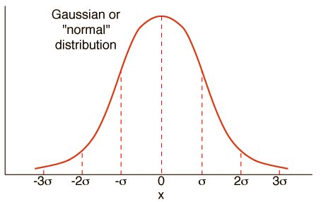
Below is a typical "Normal" distribution.
Choosing the correct gage for your needs!
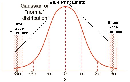
Below is an example of the 10% rule showing that the gage can use as much as 10% of your tolerance thereby protecting you from shipping or producing parts that are above or below your blue print limits. In truth these act like the old control limits first established when statistics were initially used.
Are you spending too much or not enough for your gages?
What we see in many cases is requests for attribute gages like Go NoGo gages and fixed limit gages specifying tolerance levels much tighter than what might be necessary. In addition, when using Go NoGo gages that are constantly contacting the part surface, wear is inevitable.
This presents a choice of allowing as much of the tolerance as possible to be passed, say using 10% or less of the tolerance with the gage or extending the life of the gage members by using 10-15 or even 20% of the part tolerance with a lower class of gage.
What Class of Gage Is Correct?
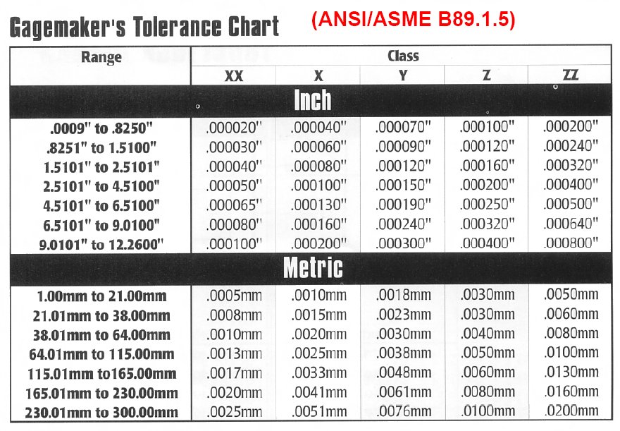
Good Question. If you use the 10% rule look at the chart shown above and take 10% of your Unilateral single sided tolerance multiply by 10% and you have a general guideline (example Tolerance is +/- 0.005" * .10 = .0005" per member if you are using a Go & NoGo gage set. Remember that these values are subtracted and added to Plugs and rings in reverse. Use the link provided to open a PDF with more explanations.
Go plug you add the tolerance to make the Go end slightly larger than the limit in order to be assured that no product that the Go plug fits into is undersized. The NoGo is the opposite you subtract the tolerance from the target and because it is now slightly under the target value if it does not go in the bore you are certain nothing that is oversized will be rejected.
This method has one drawback that you may actually reject parts that are at the very limit of the tolerance due to these tolerances added or subtracted from the functional gages,
Click Here For Gage_Makers_Tolerance_Chart.pdf
Lets Talk About Attribute gages:
Like Go / NoGo style Thread Gages or Plain Gages. When we say they are functional, we mean that literally. For instance, if you produce an internal thread form like a threaded hole, you start typically with a drilled hole. The basic hole must be within a specified Minimum and Maximum diameter before you run a tap into it in order to be assured that the finished thread form will be acceptable. By running a Go plain plug into the hole you are checking the hole functionally. Not only is the diameter within the acceptable limits but the hole is normally round and cylindrical the length you check it, making sure the tapped threads are going to be uniform and to specification fro that full depth.
Thread gages check for functional conformance so if the Go enters the tapped hole normally, and the NoGo does not enter the hole you have confirmed that the lead angle, pitch diameter, thread crest and thread root are within an acceptable stack up of tolerances and the thread form will function as designed.
One note of caution, we see questions quite often about thread gages where the Go thread plug will not go into the part while the NoGo will enter the part. This emphasizes the need to use both the Go and NoGo thread plugs every time. A typical situation that can cause this unusual situation is that the root of the product thread is shallow and the Go gage thread crest bind as you screw it in stopping entry. This combined with undersized pitch diameter allows the NoGo gage to enter the thread so it does not seem to make sense. NoGo thread gages have the crest of the thread ground down for extra clearance since the assumption is that the Go gage checked the PD, Lead Angle and Root when it was used so no need to recheck the root with a NoGo.
Stay tuned for updates.
Go Directly to the Web Store Back Home
NOTICE: All information provided on this reference sheet is intended to be for general guidelines and may not represent the full
specifications or instructions as outlined within ASME requirements or other technical specifications which govern the manufacturing and use of thread measuring gages.
thegagestore.com/LEECO INC, does not represent this information as anything
except a common sense general set of guidelines. You must always follow
the technical specifications relative to the gage, thread design or
other related gage attributes and usage that apply. When in doubt always acquire
the current specification from
http://www.asme.org/ codes & standards.
IF YOU
HAVE QUESTIONS OR COMMENTS, E-MAIL
Technical@thegagestore.com
OR FAX US AT 860-404-8903